

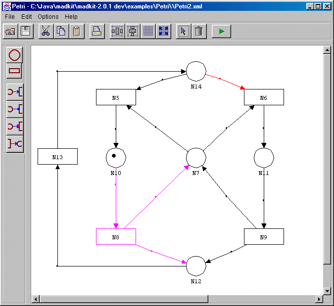
SEdit stands for Structure Editor. It is a software tool dedicated to the design and animation of structured diagrams. A diagram is made of nodes and arrows. Nodes and arrows are called elements. An arrow connect two nodes. A diagram can be seen as a directed graph in graph theory. Diagrams are categorized into types called formalisms in the SEdit terminology. A formalism describes both the structural aspect (the types of nodes and arrows, their relationship and their behavior) and the graphical aspect (the way nodes and arrows are graphically represented on the editor) of diagrams. SEdit comes with a set of pre-defined formalisms (see the list of available formalisms for details), but users can describe their own formalism (see the section defining a new formalism for details). Here are two different diagrams:
 |
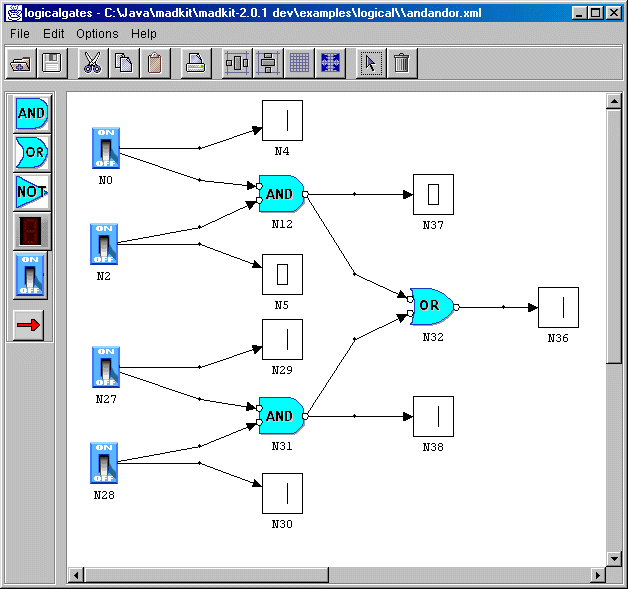 |
Figure 1. Two diagrams using SEdit. The left diagram shows a Petri formalism diagram, while the right one shows a logical gates formalism diagram. Click on the figures to get a bigger full size image.
Diagrams may be displayed, arranged and modified in various ways using the editor diagram which is represented in figure1. It is also possible to associate Java classes to arrows and nodes (and also to diagrams seen as a whole) and animate those diagrams. For instance in the Petri formalism, it is possible to design Petri nets and simulate their behavior. In the following sections we will explain how to use the editor with pre-defined formalisms and how to build your own formalisms.
Download the application from the SEdit site and unzip it.
To start SEdit, if you are on a Winxx platform, double click on the sedit.bat file. On Unix based platforms (including Linux and MacOS X), use the shell and type ./sedit.sh (make sure that the file sedit.sh is executable. Do chmod +x sedit.sh if necessary).
Once launched the SEdit application appears as a single Window, from which you may start a new diagram, using a predefined formalism, and load existing diagrams. By double clicking on one of the the formalisms icons, you will open a new diagram with an empty formalism.
(a) SEdit main view |
(b) An empty diagram using the automaton formalism |
|---|
To load an existing diagram (a .sed file) use the File>open menu or click on the open file icon.
There are several way to load a diagrams from MadKit:
It is also possible to add a button to the desktop. See the MadKit desktop user guide (if this link does not work try the online documentation at www.madkit.org) to know how to configure the desktop and add icons or menu items for .sed and .fml files. The default desktop.ini file contains some examples to understand how to make the desktop suit your needs.
It is possible to load a diagram from the explorer. You only have to double click on file with extension .sed from the explorer. The following screenshot, shows the file "fubar", a structure created with the automaton formalism, launched directly from the desktop.
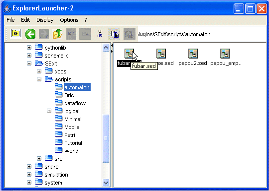
It is also possible to load an empty diagram by double clicking an formalism
file (extension .fml). Formalisms files are generally located in the lib/formalisms/
directory, as it is shown on the following figure:
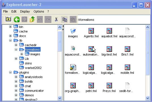
See the section defining a new formalism to learn how to make a new formalism and make it available as a preloaded formalism.
It is possible to load diagrams from the desktop by opening the "execute script dialog". This commands open a load file dialog. Diagrams (.sed files) and formalisms (.fml) files may be loaded directly as in the explorer.
The following view shows the diagram editor windows (while editing a diagram of formalisms "automaton").
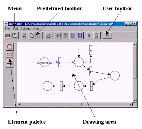
The menu and the predefined toolbar contains the generic commands and tools that are available for all diagrams in every formalisms. When you click one of the button of the toolbar, a short description of its use is displayed. All commands and tools available in the toolbar can also be accessed from the menu.
The user toolbar contains a set of tools which may be defined for a specific formalism. The drawing area is where drawing of nodes and arrows takes place. The element palette contains the set of nodes and arrows that may be added to a diagram. The elements in the palette are formalism specific.
|
Icon
|
Menu item
|
Description
|
|
|
Insert XML | Opens a dialog box to choose the directory and file you want to insert. All nodes and arrows of the selected file will be added to the current diagram. This will work only if the formalisms of the selected file and of the current diagram are compatible. |
|
|
Save XML | Saves the current diagram in a XML format. If the diagram is new, a dialog box is opened and the user can choose the directory and name of file to save the diagram. |
| Save as XML | Opens a dialog box to select a directory and name of file to save the current diagram. | |
|
|
Opens a dialog box to print the current diagram. | |
| Close | Closes the editor of the current diagram. | |
|
|
Cut | Cut the selected nodes and arrows and place them in the clipboard. |
|
|
Copy | Copy the selected nodes and arrows and place them in the clipboard. |
|
|
Paste | Paste the nodes and arrows of the clipboard and place them in the current diagram. Nodes and arrows should be compatible with the current diagram. |
|
|
Clear | Delete the selected nodes and arrows. |
| Toggle connectors display | Show/do not show, labels of connectors. | |
| Toggle nodes display | Show/do not show labels of connectors. | |
| Toggle arrows display | Show/do not show labels of arrows. | |
|
|
Align horizontally | Align the selected nodes and arrows horizontally. |
|
|
Align vertically | Aligne the selected nodes and arrows vertically. |
|
|
Show grid | Show/do not show a grid. |
|
|
Snap to grid | Snap/do not snap nodes and arrows to a grid. |
|
|
Select mode | Put the drawing area in select mode. Then it is possible to move around nodes and arrows. |
| About | Open an information box with informations about the current formalism. |
To start creating a new diagram, click on the tree formalisms of the launcher window and select a formalism. This will create a new window with an empty diagram.
A diagram is made of elements, nodes and arrows, which are organized into a structure. Nodes and arrows types are given in the element palette.
To add a new node, select its type from the element palette. This will change the cursor to become a '+'. Then click anywhere on the drawing area to add new nodes of the selected type.
To add an arrow, select its type from the element palettte. This will change also the cursor to become a '+'. Then click on the first node (the source node) and drag the mouse to the second node (the target node).
To select one node, just click on it. To select one arrow click on the joint (the point of articulation).
To select a set of nodes and arrows, click on the mouse somewhere on the drawing area and draw a rectangle around them. All nodes whose center are in the this rectangle, and all arrows whose joint are also in the selection area will be selected.
Using the combination shift-click, it is possible to add new nodes to this selection.
Nodes and arrows can be moved around by simply selecting them and dragging them to a new location.
Each element has a set of actions which can be performed on it. To see the set of possible actions, right click on a node or right click on the joint of an arrow to select it. A pop-up menu will appear. Select one of the actions to execute it.
The following figure shows the standard actions available for all elements:
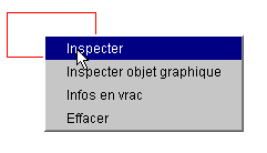
The standard actions are:
The action 'inspect' opens a property editor in which it is possible to modify values. To modify a value, just enter the value you want to modify in one of the fields and validate the modification by clicking on the button on the right of the field. This property editor shows the properties of the elements themselves. The graphic properties are described below.
Here is the standard property editor:
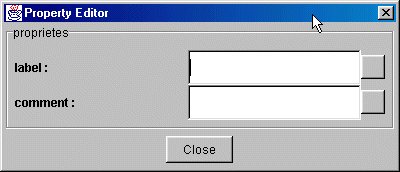
Different types of elements may have other fields. For instance, here is the property editor of a transition in the Petri formalism. This editor includes the fields predicatestring and actionstring which may be used to describe a colored transition in Petri.
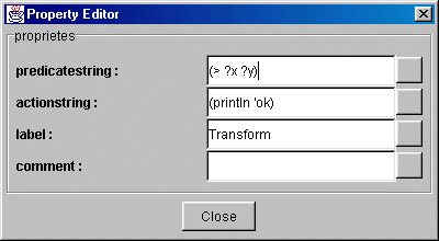
To learn how to add new actions to nodes and arrows, and to add properties to the property editor, see the section defining a new formalism.
The action 'Graphic inspect' opens a property editor dedicated to graphics properties of the element. Here is a graphic editor which applies to simple graphic elements. It is possible to modify the dimension of the element, to activate or deactivate the display of the 'label' (i.e. the name) of an element, and to modify the location of the label.
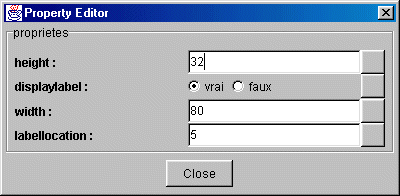
Here is the graphic editor of iconic based elements:
![]()
This adds the field 'imageaddress'. It is then possible to modify directly the image of a specific icon.
Does nothing for the moment...
Delete the selected element and remove it from the diagram.
To save a diagram, use the command 'Save' or 'Save as' from the file menu, or click on the save icon. The 'Save as' command opens a file dialog and let the user choose a directory to save the diagram.
One of the key feature of SEdit is its ability to define new formalisms. It is possible to change both the graphical design of elements and the behavior of elements. The general organisation of a formalisms is given in an XML file generally located in the 'lib/formalisms/' folder. To learn how to make your own formalism, see the file dedicated to formalisms.
SEdit is an extension of MadKit. While able to work alone, SEdit takes its full power in working as a companion to MadKit.
{{to be continued}}