Contents
1
Main
commands
2
Views
3 Editors
4 Keyboard shortcuts
The CoGui workbench is divided into a number of views. A view has the functionality of a window. Depending on the type of the view it can be closed (sometimes allowed), minimized (sometimes allowed), maximized (always allowed). Views are also dockable/undockable and the windows layout is user customizable. Unlike editors, each type of view has only one instance with a particular behaviour. In the following sections we will first give general information about view management, and then a description of particular behaviour for each kind of view.
The default windows layout keeps every view inside a main window (which contains the main menu and the tool bar). However, the user can place one or more views in a floating window somewhere on the screen, independently of main window. The user can also drag a view outside the main window, and in this case a floating window containing the view will be automatically created.
It is also possible to drag and drop views inside the main window in order to conveniently arrange views.
Once the users are satisfied with the layout they can easily save their settings which will be restored the next time the application is started. In the main menu the option "View/Save current layout" saves the new layout, size and position of each view to automatically restore it later. It is always possible to retrieve default windows layouts presented in paragraph 2.1 with the option "View/Restore default layout".
1) Left panel contains the project,the types and the individuals views
2) Bottom panel contains the error, the result and the property views
3) Center panel contains the task view and the editors
Each view has a unique instance and a particular behaviour in
the application, in this chapter we will describe each type of view.
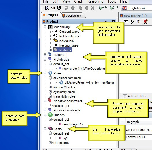
The project view gives access to the different objects of the project in a project tree.
project view
the error view
2.4.5
Individual view
Each kind of graph editor has its own vertices factory:
* Concept type hierarchy allows insertion of concept types
* Relation type hierarchy allows insertion of relation types
* Nesting type hierarchy allows insertion of nesting types
* Other editors (fact graphs, rules, pattern graphs, prototypic graphs, individual graphs) allow insertion of concept and relation vertices
Vertices can be added to the graph by using either the menu "Graph/Insert vertex" option or local toolbar buttons. But the easiest way to place vertices at mouse position is to right-click and choose insert menu options in the contextual menu. It is also possible to drag a type (or several types) from type view trees to the editor or to drag an individual from individual view table to the editor.
3.2
Editing graphs
Selection
Just click on a vertex to select it. Selected vertices
can
easily be
recognized by the handles decorating them. Hold down the left mouse
button to
select an area: all objects (vertices and edges) entirely
contained in this area will be selected. It is useful to do
multiple
selection to move a large part of the graph with only one operation.
Another reason to select several vertices is that they remain fixed
during the Spring Layout. In the case of multiple
selection the property view remains empty.
Selected vertices can be copied, cut and pasted in a graph editor or from an editor to another. Edition commands are accessible from main menu, toolbar, contextual menu and via keyboard shortcuts.
Drag'n'drop
Drag and drop is a very useful feature to speed up
edition
process. Several kind of drag'n'drop possibilities are proposed in
Cogui:
Three layouts are preavailable. The algorithms provided to arrange type hierarchies cannot support circuits. The Spring Layouter uses a force-based layout and can be used everywhere.
3.3
Inline edition
Double click on a vertex edits its content (more
precisely
parameters that are most often used in current language). You can also
click on the upper
left corner. The popup
dialog is more (concept) or less (concept type) sophisticated, it
depends on the nature of the vertex.This is the easiest way to edit
vertices.
The nature of edges depends on the type of edited graph. However, this
time, the nature of vertices is enough to guess the nature of the edges
that will connect them, ensuring no ambiguity.
The different types of edges are:
To create a new edge, just place the mouse pointer on port placed at the center of the source vertex: the shape of the mouse pointer is automatically modified and replaced by a hand .
Then
press on the left button of
the mouse and release it when you have reached the target vertex. Note
that the order is only important for the "kind of" link between types,
for the other edges, it makes no difference. It is always possible to
change the source or target vertex after creation by using one of the
two handle of a selected edge.
.
Then
press on the left button of
the mouse and release it when you have reached the target vertex. Note
that the order is only important for the "kind of" link between types,
for the other edges, it makes no difference. It is always possible to
change the source or target vertex after creation by using one of the
two handle of a selected edge.
3.5
Lexicographical search on graph
The graph editor has its own lexicographical search
tool. Press Ctrl-F to popup a search toolbar at the bottom of
the editor.
3 Editors
4 Keyboard shortcuts
1 Main commands
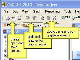
CoGui provides a classical frame GUI with a main menu and a toolbar.1.1 Main menu
 |
The File menu allows to open and save projects in COGXML format. |
 |
The Edit menu provides Undo/Redo mechanisms for graphs / rules editors. Please note that each editor has its own history of commands, and the undo and redo will only apply to the selected editor. The selection of objects, as well as the copy and paste commands also concern editing graphs and rules. |
 |
The View menu provides actions for both view management and visual effects inside the editors. |
 |
Commands inside the Graph menu only concern building and modifying the graph-based editors. All these commands can be activated directly inside editors with widgets, contextual popup menus and keyboard shortcuts (see chapter 1.3). |
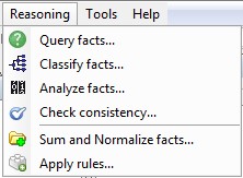 |
Reasoning menu gives access to the assistants for querying and applying rules and different algorithms on knowledge base |
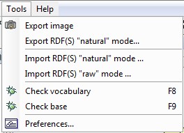 |
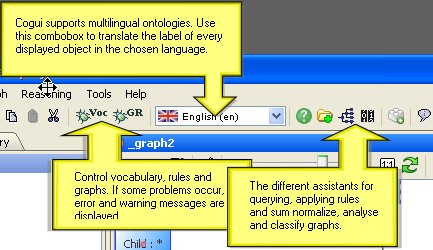
Tools menu allows to export graph images, import and export RDF(S) data, control vocabulary and facts as well as access preferences. |
 |
This allows users access to documentation and informations about LIRMM-RCR team. |
1.2 Main toolbar
the main toolbar
2 Views
The CoGui workbench is divided into a number of views. A view has the functionality of a window. Depending on the type of the view it can be closed (sometimes allowed), minimized (sometimes allowed), maximized (always allowed). Views are also dockable/undockable and the windows layout is user customizable. Unlike editors, each type of view has only one instance with a particular behaviour. In the following sections we will first give general information about view management, and then a description of particular behaviour for each kind of view.
2.1 Default view layout
figures below present the views in the default application layoutdefault view layout (1)
default view layout (2)
default view layout (2)
2.2 Docking windows framework
 view title bar buttons
|
Users can customize the layout of the application
according to
their preferences. Users can minimize, maximize, close, dock,
undock and move around the windows to create a personalized windows
layout. The title bar of each view is provided with buttons on the
right
corner. Depending on the type of view some buttons can be hidden. |
 |
A double click on the view title bar directly maximizes the view. If it is already maximized, it will retrieve its original size. |
The default windows layout keeps every view inside a main window (which contains the main menu and the tool bar). However, the user can place one or more views in a floating window somewhere on the screen, independently of main window. The user can also drag a view outside the main window, and in this case a floating window containing the view will be automatically created.
It is also possible to drag and drop views inside the main window in order to conveniently arrange views.
 |
This animation shows how to arrange views inside the main window. |
Once the users are satisfied with the layout they can easily save their settings which will be restored the next time the application is started. In the main menu the option "View/Save current layout" saves the new layout, size and position of each view to automatically restore it later. It is always possible to retrieve default windows layouts presented in paragraph 2.1 with the option "View/Restore default layout".
|
Note that views are not closeable in the main window but can be closed in a floating window. If a view is closed, it is possible to retrieve it with the option "View/Show view" in the main menu. |
2.3 Tabbed Panels
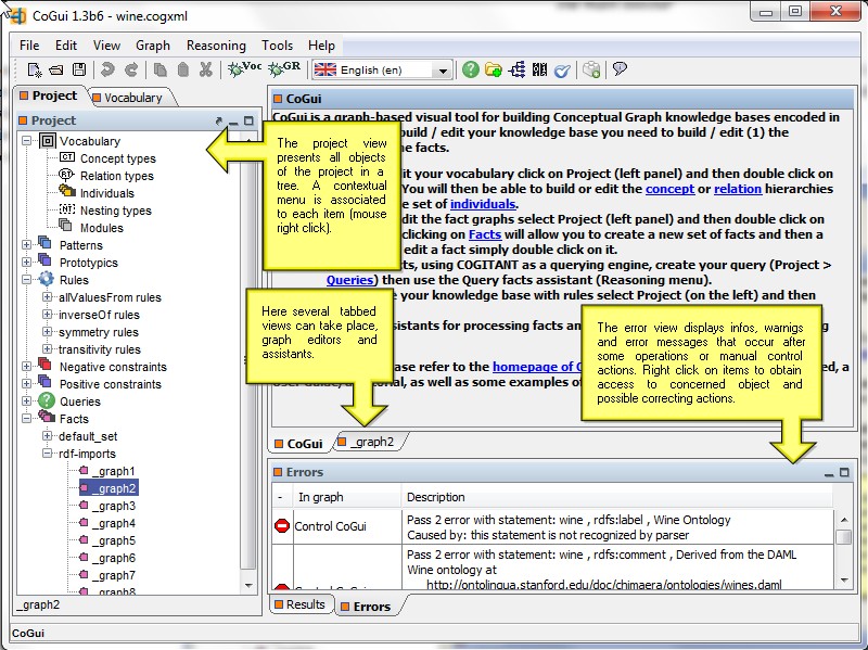
Default view layout provides three tabbed panels.1) Left panel contains the project,the types and the individuals views
2) Bottom panel contains the error, the result and the property views
3) Center panel contains the task view and the editors
 contextual menu on tabs |
Tabs can be placed on either side of the center panel. The titled tabs can be rotated 90°, 180° and 270° thus making it possible to have vertical texts and icons. You can even reorder tabs using the mouse. All these features are provided by the contextual menu (right click on tab). These preferences can be saved with the same mechanism as windows layout: options "View/Save current layout" and "View/Restore default layout" in main menu. |
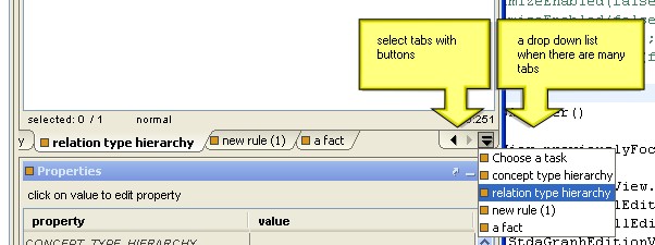
Buttons and a drop down
list of all the tabs could simplify the
selection of a tab in the case where there are too many tabs.
tab selection
2.4
Views descriptions
Each view has a unique instance and a particular behaviour in
the application, in this chapter we will describe each type of view.2.4.1 Project View
The project view gives access to the different objects of the project in a project tree.
project view
Actions on the project tree
Each element of the tree is associated with a context menu accessible by right click. Please find below a table listing all the possible actions from these menus.| Item | Action | Description |
| Concept types/ Relations types/ Nesting types | Edit types: tree view | Show the type tree panel in concept type view, respectively in relation type view and nesting type view |
| Graphical editor | Open an editor containing the graphical representation of the type hierarchy | |
| Modules | New module | Create a new module |
| Rules | New set of rules | Create a new set (folder) of rules |
| Rule set item | New rule | Create a new rule inside inside the currently selected rule set |
| New set of rules | Create a new sibling set (folder) of rules | |
| Rename set of rules | Rename the set of rules | |
| Delete set of rules | Delete current rules set and all the rules contained in it | |
| Rule item | Edit rule | Open an editor containing the graphical representation |
| New rule | Create a new sibling rule | |
| New set of rules | Create a new set (folder) of rules. Note that there is only one level of folder. So the new folder is a child of 'Rules' item and not a sibling of the currently selected rule. | |
| Rename | Rename the currently selected rule | |
| Delete rule | Delete the currently selected rule | |
| Queries | New set of queries | Create a new set (folder) of graph queries |
| Query set item | New query | Create a new query inside the currently selected set |
| New set of queries | Create a new set (folder) of queries. Note that there is only one level of folder. So the new folder is a child of 'Queries' item and not a sibling of the currently selected set of fact. | |
| Rename set of queries | Rename the set (folder) of queries | |
| Delete set of queries | Delete the currently selected set of queries and all facts contained in it | |
| Query graph item | Edit | Open an editor containing the graphical representation of the corresponding conceptual graph |
| Edit whole graph | Open an editor containing the graphical representation of the corresponding conceptual graph. Force all vertices to be displayed and forbid reduced edition usage | |
| New query | Create a sibling new query graph | |
| New set of queries | Create a new set (folder) of fact graphs. Note that there is only one level of folder. So the new folder is a child of 'Facts' item and not a sibling of the currently selected graph. | |
| Rename | Rename query | |
| Delete | Delete query | |
| Facts | New set of facts | Create a new set (folder) of graph facts |
| Fact set item | New fact | Create a new fact inside the currently selected set |
| New set of facts | Create a new set (folder) of facts. Note that there is only one level of folder. So the new folder is a child of 'Facts' item and not a sibling of the currently selected set of fact. | |
| Rename set of facts | Rename the set (folder) of facts | |
| Delete set of facts | Delete the currently selected set of facts and all facts contained in it | |
| Fact graph item | Edit | Open an editor containing the graphical representation of the corresponding conceptual graph |
| Edit whole graph | Open an editor containing the graphical representation of the corresponding conceptual graph. Force all vertices to be displayed and forbid reduced edition usage | |
| New fact | Create a sibling new fact graph | |
| New set of facts | Create a new set (folder) of fact graphs. Note that there is only one level of folder. So the new folder is a child of 'Facts' item and not a sibling of the currently selected graph. | |
| Rename | Rename fact graph | |
| Delete fact | Delete fact graph |
|
A double-click on the selected element triggers the following action by default: depending on the type of the element it either displays the view of the corresponding hierarchy or it opens the editor of the selected element. |
Search for elements in the project tree
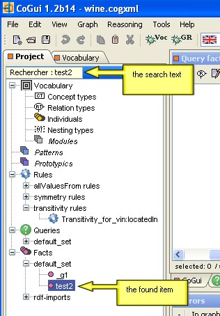
The tree project has a search tool. It is thus possible to find anything using its label as a search string. To do this, please make sure the project view is selected and then type the first letters on the keyboard: the first element of the tree beginning with those letters will be automatically selected. If the item is hidden, some elements of the tree will be expanded so that it becomes visible. In addition, if several elements correspond to the query, just use the arrow keys to scroll.searching in project tree
Each type hierarchy is displayed in a specialized view (concept type view, relation type view and nesting type view). And it is associated with a context menu accessible by right click.
Tool Bar
The type views have a tool bar with actions listed below:
|
The search tool supports generic characters such as '*' and '?'. For instance "*pro" will find all items containing the string "pro" such as "approach". |
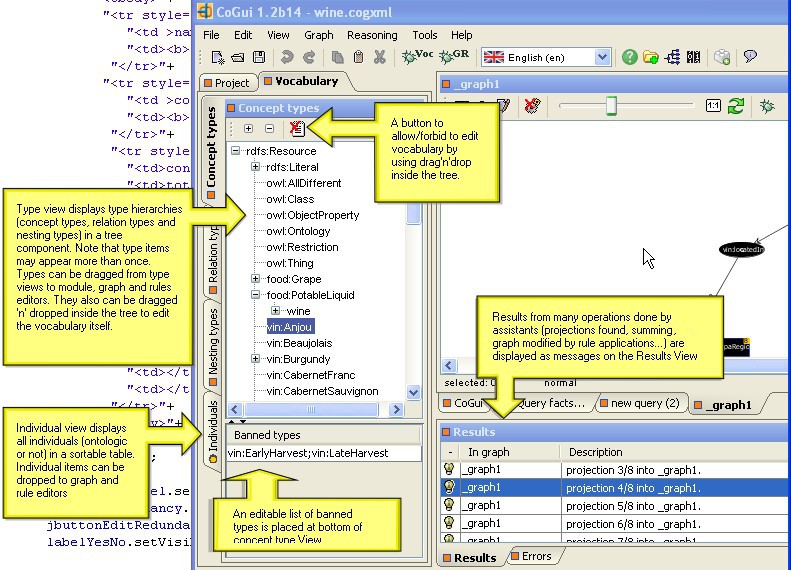
2.4.2 Type views
Each type hierarchy is displayed in a specialized view (concept type view, relation type view and nesting type view). And it is associated with a context menu accessible by right click.
 |
 |
 |
 |
These views provide a representation in the tree-like structure. But hierarchies of concept types and relation types are not necessarily trees, therefore duplication might occur. |
Tool Bar
The type views have a tool bar with actions listed below:
| Action | Description |
 expand
all items of
the tree expand
all items of
the tree |
Open an editor containing the graphical representation of the type hierarchy |
 collapse all items
of the tree collapse all items
of the tree |
CoGui can create multilingual ontologies. This action helps to describe the labels and descriptions of each type in several languages. |
 activate/inhibit drag and
drop inside the tree activate/inhibit drag and
drop inside the tree |
This feature locks/unlocks the ability to update the tree directly by using drag and drop. Note that this lock concerns only the internal drag'n'drop actions, the tree types can always be dragged from the views to the editors. |
|
To use drag'n'drop, note that it is possible to select multiple types in the tree. For this, keep the Ctrl key down. |
Lexicographic search in types trees
 search a type by label
|
The type view benefits from a search tool. It is thus possible to find a type by its label. To do this, make sure that the type view is selected then type the first letters on the keyboard: the first element of the tree beginning with those letters will be automatically selected. If the item is hidden, some elements of the tree will be expanded so that it becomes visible. In addition, if several elements correspond to the query, just use the arrow keys to browse through the different found types or the different paths for the same found type. |
|
The
search tool
supports generic characters such as '*' and '?'. For instance "*animal"
will find all types containing the string "animal". Note that relation type view items display the signature of each relation type but this signature is not taken into account by the search. |
 |
2.4.3 Error view
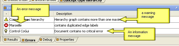
The Error view displays a list of messages. These messages are generated by the control of the project. This control is triggered either (1) manually by the "control" button or (2)automatically, at the opening of the project or (3)before carrying out certain tasks (querying for example).the error view
There are three kinds of
messages.
The table is sortable: click on the column header to choose the sorting
criteria. A contextual menu is associated with each message. The option
"Show it on graph" opens the editor associated with the concerned
objects, and the objects are highlighted in red on the editor.
Sometimes
it is possible to automatically correct the error (or warning). When it
can be done, the correction action is added to the contextual menu.
 |
information message |
 |
warning message |
 |
error message |
|
A double click on an error message opens the editor and hightlights the concerned objects, an easy way to correct errors on graphs. |
2.4.4 Result view
| This view contains the result of some assistant operations. When projections (potential answers for the query) are found, they are listed in the table: |  |
| Graphs produced by sum and normalization assistant are also displayed in the result view. Note that graphs provided by the assistants are not automatically added to the project, they must be dragged from the result view to the project view to be regsitered and saved. |  |
the result view
|
A double click on a query anwer opens the corresponding editor and hightlights the projected vertices. |
|
Graphs provided by assistants in the result view are draggable |
2.4.5
Individual view
| The Individual view
lists
all the individuals in a
sortable
table. Click on the header column to sort. Individuals could be dragged from the list to the editors. Use contextual menu to edit to the corresponding individual graph. If the graph doesnt exist, it is automatically created. |
 |
3 Editors
Unlike views, editors are closeable, they can not be moved, they are always placed in the central panel. Editors provide a graphical way of modifying the objects of the model. With the exception of the module editor (a table), they use the graph representation. Most objects in the model are graphs and are edited in a graph-based editor. Of course, each edition has its own features, but most of the editing functions are common, and in this chapter we will describe them.3.1 Vertex insertion
Each kind of graph editor has its own vertices factory:
* Concept type hierarchy allows insertion of concept types
* Relation type hierarchy allows insertion of relation types
* Nesting type hierarchy allows insertion of nesting types
* Other editors (fact graphs, rules, pattern graphs, prototypic graphs, individual graphs) allow insertion of concept and relation vertices
Vertices can be added to the graph by using either the menu "Graph/Insert vertex" option or local toolbar buttons. But the easiest way to place vertices at mouse position is to right-click and choose insert menu options in the contextual menu. It is also possible to drag a type (or several types) from type view trees to the editor or to drag an individual from individual view table to the editor.
3.2
Editing graphs
Selection
Just click on a vertex to select it. Selected vertices
can
easily be
recognized by the handles decorating them. Hold down the left mouse
button to
select an area: all objects (vertices and edges) entirely
contained in this area will be selected. It is useful to do
multiple
selection to move a large part of the graph with only one operation.
Another reason to select several vertices is that they remain fixed
during the Spring Layout. In the case of multiple
selection the property view remains empty. |
This animation shows how to select and move several objects |
|
To add or remove an object from the selection set, keep Shift key pressed. |
Copy, Paste
Selected vertices can be copied, cut and pasted in a graph editor or from an editor to another. Edition commands are accessible from main menu, toolbar, contextual menu and via keyboard shortcuts.
|
Pending edges are not allowed in selection set. Thus an edge can only be copied if its source and target vertices are also selected. |
Drag'n'drop
Drag and drop is a very useful feature to speed up
edition
process. Several kind of drag'n'drop possibilities are proposed in
Cogui:- Vertices can be dragged and dropped inside the graphical editors.
- Types can also be dragged from type tree to graph based editors. If the edited object is a conceptual graph or a rule, the copied object is created with the dragged type (i.e. dragging a concept type creates a concept of this type etc.)
- Individuals can be dragged from the individual view to graphs and rules editors. A new concept is created on the graph with the dragged individual. The privileged type of the individual is used to type the new concept by default.
- Types can be dragged and dropped inside the types tree
views.
To
avoid
some unexpected actions, drag and drop is disabled by default inside
the type view. Activate it by pressing the bouton on the local toolbar of
the type view.
- Graphs
and rules can be drag and drop inside the project tree. To avoid some
unexpected actions, drag and drop is disabled by default inside the
type view. Activate it by pressing the bouton on the local
toolbar.
- Graphs produced by the "sum and normalize assistant" are placed in the result view. These graphs can be dragged from the result view to the projet view
- Types can be dragged from a type tree view to a module
|
Simple drag and drop in the projet view and the hierachy views will move the selected resource (type, graph, rule,...) into the tree. But pressing Ctrl button before releasing the left mouse button will add a copy of the selected resource. It is the simplest way to obtain clones of existing graphs (or existing rules). |
Automatic arrangements
Three layouts are preavailable. The algorithms provided to arrange type hierarchies cannot support circuits. The Spring Layouter uses a force-based layout and can be used everywhere.
 |
Arrange hierarchy horizontally |
 |
Arrange hierarchy vertically |
 |
Spring Layouter is ON |
 |
Spring Layouter is OFF |
|
Because the two algorithms for arrangement of hierarchies do not work with circuits, so they generally can not be used with the graphs and rules. |
3.3
Inline edition
Double click on a vertex edits its content (more
precisely
parameters that are most often used in current language). You can also
click on the upper
left corner. The popup
dialog is more (concept) or less (concept type) sophisticated, it
depends on the nature of the vertex.This is the easiest way to edit
vertices.
 edition
of a
concept type
|
 edition
of a
relation type
|
 edition
of a concept
|
 edition
of a
relation
|
|
Depending on the characters already entered, the fields of concepts and relations provide a list of compatible types and individuals. For conjunctive concept types please enter a new line for each type. |
The different types of edges are:
| edge between a concept and a relation (numbered) |  |
| coreference link between concepts representing the same object | 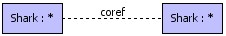 |
| oriented edge to express "kind of" relation between types. |  |
| correspondance link between a concept placed in the hypothesis of a rule and a concept placed in the conclusion of this rule. |  |
To create a new edge, just place the mouse pointer on port placed at the center of the source vertex: the shape of the mouse pointer is automatically modified and replaced by a hand
.
Then
press on the left button of
the mouse and release it when you have reached the target vertex. Note
that the order is only important for the "kind of" link between types,
for the other edges, it makes no difference. It is always possible to
change the source or target vertex after creation by using one of the
two handle of a selected edge. |
By
default ports placed at the center of each vertex are visible, ports
can be hidden and connection mode turned off with the button  / /  on the
graph
editor toolbar. on the
graph
editor toolbar. |
3.5
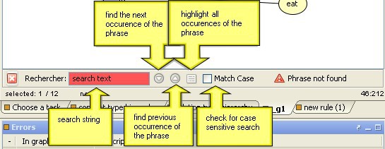
Lexicographical search on graph
The graph editor has its own lexicographical search
tool. Press Ctrl-F to popup a search toolbar at the bottom of
the editor.
4 Keyboard shortcuts
| Copy selected objects | |
| Paste | |
| Cut | |
| Popup the search toolbar | |
| Delete selected objects (when a vertex is deleted all edges connected to it are also deleted) | |
| Edit current vertex | |
| Refresh | |
| Control vocabulary | |
| Control base | |
| Use mouse wheel with Control key to zoom in or zoom out inside the graphical editors |